Who created this, how it was made and why it exists
- Who
- Published under the organizational identity Pergola Wiki Editorial Team; neither AI nor the organization is presented as a named professional individual.
- How
- AI assistance was used for drafting, translation, source-metadata organization, static-site coding and automated QA in a publisher-directed workflow. Automated checks do not establish technical correctness.
- Why
- To provide free bilingual educational synthesis; one disclosed Oscar Pergola industry link does not determine conclusions, source tiers or rankings.
Read a detailed text description
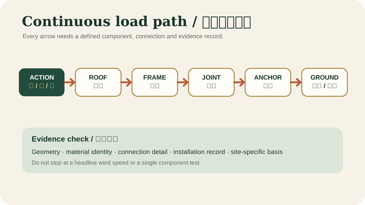
The diagram follows gravity, wind uplift and lateral actions from the roof surface into rafters or louvers, beams and posts. It continues through every connection, base plate and anchor into the foundation and finally the supporting soil, emphasizing that one weak or undocumented link interrupts the claimed structural path.
Key takeaways
- Every reaction needs a destination.View claim record ·
PWC-STRUCTURAL-LOAD-PATH-1 - The weakest concealed connection can govern.View claim record ·
PWC-STRUCTURAL-LOAD-PATH-2 - Screens, roofs and attachments change the path.View claim record ·
PWC-STRUCTURAL-LOAD-PATH-3
The claim register connects stable IDs, article locations and article-level associated sources; it is not an external fact-check of each statement.
On this page
Start with actions
Gravity from self-weight, maintenance and snow moves downward; wind can push, pull upward and twist; seismic motion creates inertia; rain can add water weight and ponding effects. Thermal movement and operation create additional compatibility demands even when they are not primary strength actions.
Follow each interface
Trace panel or louver to rafter, beam, post, base plate, anchor, concrete and soil. For an attached system, also trace the ledger or bracket into verified building framing and then through that building’s resisting system. Naming a strong beam does not verify the screws, thin extrusion walls or foundation beneath it.
Official standard hub for US structural actions including wind, snow, rain, seismic and load combinations.
Stability is a system property
A rectangular frame needs moment resistance, diagonal bracing, shear panels or another defined lateral system. Tall posts and narrow bays amplify movement. Decorative corner brackets provide structural resistance only when their material, geometry and connections are designed for the demand.
Create a verification drawing
A one-page load-path diagram should mark member identities, connection types, reactions, design actions, movement joints and responsibility boundaries. Pair it with calculations and installation records. This diagram becomes especially valuable when later adding screens, heaters, solar panels or a roof.
US model-code provisions for residential patio covers; only applicable where adopted.
Check resistance and compatibility together
A complete load path is more than a list of strong parts. Adjacent components must also have compatible stiffness and movement. A rigid roof panel on a flexible frame can attract local force or lose seals; a strong anchor in a thin extrusion can tear the surrounding wall; a stiff attached frame can transfer movement into an existing façade. Calculations, connection details and movement allowances should describe the same physical model. Screens, heaters, solar modules and ceiling panels must be added to the load-path drawing before every downstream connection and foundation is checked.
Load-path verification matrix
Verify every hand-off from environmental action to ground.
| Checkpoint | Define | Retain |
|---|---|---|
| Roof to rafter | Panel/louver reactions | Fasteners and local section |
| Rafter to beam | Shear, uplift and rotation | Connection detail |
| Beam to post | Moment and stability | Joint stiffness |
| Post to ground | Base reactions | Plate, anchor, concrete, soil |
Evidence check before acting
This article provides general educational synthesis; these three checks turn reading into project-specific verification work.
| Confirm | Stronger evidence to retain | What this article cannot establish |
|---|---|---|
| Site actions, continuous load path, foundations, connections and supporting structure | Project-specific site data, calculations, approved drawings and inspection records | A general table, calculator or article is not a project design or approval. |
Registered cited sources and scope
Official standard hub for US structural actions including wind, snow, rain, seismic and load combinations.
US model-code provisions for residential patio covers; only applicable where adopted.
European framework for actions including self-weight, imposed, snow and wind actions.
European framework covering resistance, serviceability, durability and fire resistance of structural aluminium.
Cite this page
Pergola Wiki Editorial Team. “Structural load path: roof to soil.” Pergola Wiki. Content version 1.7; editorially reviewed 25 Jul 2026. https://pergola.wiki/articles/structural-load-path/