Who created this, how it was made and why it exists
- Who
- Published under the organizational identity Pergola Wiki Editorial Team; neither AI nor the organization is presented as a named professional individual.
- How
- AI assistance was used for drafting, translation, source-metadata organization, static-site coding and automated QA in a publisher-directed workflow. Automated checks do not establish technical correctness.
- Why
- To provide free bilingual educational synthesis; one disclosed Oscar Pergola industry link does not determine conclusions, source tiers or rankings.
Read a detailed text description
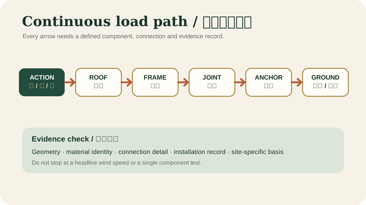
The diagram follows gravity, wind uplift and lateral actions from the roof surface into rafters or louvers, beams and posts. It continues through every connection, base plate and anchor into the foundation and finally the supporting soil, emphasizing that one weak or undocumented link interrupts the claimed structural path.
Key takeaways
- Electrical equipment needs an environmental rating, protection strategy and qualified installation.View claim record ·
PWC-LIGHTING-HEATING-AND-ELECTRICAL-INTEGRATION-1 - Cable routes and access must be coordinated before hollow sections and roof cavities are closed.View claim record ·
PWC-LIGHTING-HEATING-AND-ELECTRICAL-INTEGRATION-2 - Heaters, fans and luminaires add weight, wind area, heat and maintenance demands.View claim record ·
PWC-LIGHTING-HEATING-AND-ELECTRICAL-INTEGRATION-3
New or rewritten sections in this topic use section-mapped citations; the claim register remains editorial synthesis, not external fact-checking or independent review.
On this page
- Start with the activity, not a fixture list
- Use a four-layer pergola lighting plan
- Limit glare, spill and unnecessary night lighting
- Define the real outdoor environment
- Choose a temporary, solar or fixed-wired path deliberately
- Coordinate concealed routes before closure
- Treat heat, weight and movement as design inputs
- Commission use, controls and failure states
- Keep drivers, batteries and access maintainable
Start with the activity, not a fixture list
The useful first question is what must be seen after dark: a step or route, food preparation, faces around a table, controls, or a feature that is optional to highlight. Build the smallest set of layers that answers those tasks: low, shielded route light; focused task light; dimmable ambient light; and optional accent light. A decorative string, pendant, strip or post light is an implementation choice, not proof that the task, glare or safety problem has been solved.
Government principles for necessary, targeted, shielded, controlled, low-level and warmer outdoor lighting in park settings. They inform glare and light-spill decisions but are not a universal residential lighting code or pergola illuminance schedule.
Joint professional guidance to make outdoor lighting useful, targeted, low-level, controlled and warm-coloured. It is guidance rather than proof of local code compliance, product safety or a universal brightness value.
Use a four-layer pergola lighting plan
For circulation, keep steps, thresholds and changes of level legible without aiming a bright source into approaching eyes. For dining or work, place controlled light on the surface rather than flooding the whole roof. For ambient use, prefer indirect or shielded light that can be dimmed. For accent, light only a selected post, plant or texture and check spill beyond the property. Mock up one zone at night before repeating fittings across the structure.
Government principles for necessary, targeted, shielded, controlled, low-level and warmer outdoor lighting in park settings. They inform glare and light-spill decisions but are not a universal residential lighting code or pergola illuminance schedule.
Limit glare, spill and unnecessary night lighting
The National Park Service and the joint DarkSky–IES principles converge on five decisions: use light only when useful, aim it only where needed, keep it no brighter than necessary, control when it operates, and prefer warmer colour where practical. Those are design principles, not a universal residential code or a fixed pergola brightness value. Local nuisance, ecological, planning and electrical rules still need project-specific checks.
Government principles for necessary, targeted, shielded, controlled, low-level and warmer outdoor lighting in park settings. They inform glare and light-spill decisions but are not a universal residential lighting code or pergola illuminance schedule.
Joint professional guidance to make outdoor lighting useful, targeted, low-level, controlled and warm-coloured. It is guidance rather than proof of local code compliance, product safety or a universal brightness value.
Define the real outdoor environment
Under a pergola does not automatically mean dry. Wind-driven rain, condensation, gutter leakage, wash-down, dust, salt and insects can reach fittings and cable entries. Select equipment and enclosures for the exact exposure and local electrical rules, not a product photograph. WorkSafe New Zealand guidance for outdoor decorative lighting also separates products marked for outdoor use, secure support and licensed electrical follow-up; it cannot be transferred into a universal product rating.
New Zealand government consumer guidance on outdoor-use labels, secure attachment, weather exposure, RCD protection and licensed electrical follow-up. It does not establish requirements outside New Zealand or verify a specific product.
Choose a temporary, solar or fixed-wired path deliberately
Portable solar lanterns and removable outdoor-rated strings can reduce concealed work, but batteries, cords, supports, controls and weather exposure still need inspection. Fixed strips, downlights, sockets, fans or heaters need a services schedule covering load, location, supply, control, isolation and access. CPSC guidance on weatherproof covers and ground-fault protection is United States consumer context, not a substitute for the locally adopted wiring rules or qualified installation elsewhere.
Government consumer guidance on weatherproof covers, outdoor receptacles and ground-fault protection. Adopted electrical codes and qualified installation remain project-specific.
New Zealand government consumer guidance on outdoor-use labels, secure attachment, weather exposure, RCD protection and licensed electrical follow-up. It does not establish requirements outside New Zealand or verify a specific product.
Coordinate concealed routes before closure
Hollow posts and beams may contain reinforcing webs, fasteners, drains or moving parts. Drilling can weaken thin sections, damage finishes or block water paths. Use project-approved penetrations, bushings and access points; keep cable and drainage paths distinct, photograph routes before closure and label circuits so later maintenance does not depend on guesswork.
Official guidance for England covering structure, fire, moisture, drainage, access, electrical safety and workmanship.
Official Class 1 and 10 reference retained for jurisdictions or applications still using NCC 2022 Amendment 2. It is not evidence that the edition remains applicable to every Australian project during the NCC 2025 transition.
Treat heat, weight and movement as design inputs
Radiant heaters require verified clearances from fabric, seals, plants, finishes and occupants. Fans, pendants and suspended strings add weight, wind area and movement, and need supports verified for the actual fitting and load. Operable louvers, retractable roofs and screens create moving envelopes where cables, limits, sensors and pinch protection must be designed before installation.
Official standard hub for US structural actions including wind, snow, rain, seismic and load combinations.
Official abstract establishing a lifecycle framework from briefing and design through maintenance, replacement, reuse and disposal.
Commission use, controls and failure states
Test protective devices, isolation, dimming, timers, occupancy controls, limits, sensors, manual override and power-loss behaviour within the responsible installer’s scope. Check the night-time result from seated, standing, approach and neighbouring viewpoints. Rain or wind sensors may trigger an intended operational response, but they are not structural protection and do not authorize use in unsafe weather.
Government principles for necessary, targeted, shielded, controlled, low-level and warmer outdoor lighting in park settings. They inform glare and light-spill decisions but are not a universal residential lighting code or pergola illuminance schedule.
Joint professional guidance to make outdoor lighting useful, targeted, low-level, controlled and warm-coloured. It is guidance rather than proof of local code compliance, product safety or a universal brightness value.
Keep drivers, batteries and access maintainable
Drivers, transformers, batteries, sensors and motors can have shorter service cycles than the frame. Place replaceable parts where they remain accessible without removing structural connections or waterproofing. The handover record should identify equipment, circuits, settings, isolation, approved supports, cleaning limits, maintenance intervals and the responsible installer.
Official abstract establishing a lifecycle framework from briefing and design through maintenance, replacement, reuse and disposal.
Government consumer guidance on weatherproof covers, outdoor receptacles and ground-fault protection. Adopted electrical codes and qualified installation remain project-specific.
Evidence check before acting
This article provides general educational synthesis; these three checks turn reading into project-specific verification work.
| Confirm | Stronger evidence to retain | What this article cannot establish |
|---|---|---|
| Site actions, continuous load path, foundations, connections and supporting structure | Project-specific site data, calculations, approved drawings and inspection records | A general table, calculator or article is not a project design or approval. |
Registered cited sources and scope
Official guidance for England covering structure, fire, moisture, drainage, access, electrical safety and workmanship.
Official Class 1 and 10 reference retained for jurisdictions or applications still using NCC 2022 Amendment 2. It is not evidence that the edition remains applicable to every Australian project during the NCC 2025 transition.
Official abstract establishing a lifecycle framework from briefing and design through maintenance, replacement, reuse and disposal.
Official standard hub for US structural actions including wind, snow, rain, seismic and load combinations.
Government consumer guidance on weatherproof covers, outdoor receptacles and ground-fault protection. Adopted electrical codes and qualified installation remain project-specific.
Government principles for necessary, targeted, shielded, controlled, low-level and warmer outdoor lighting in park settings. They inform glare and light-spill decisions but are not a universal residential lighting code or pergola illuminance schedule.
Joint professional guidance to make outdoor lighting useful, targeted, low-level, controlled and warm-coloured. It is guidance rather than proof of local code compliance, product safety or a universal brightness value.
New Zealand government consumer guidance on outdoor-use labels, secure attachment, weather exposure, RCD protection and licensed electrical follow-up. It does not establish requirements outside New Zealand or verify a specific product.
Cite this page
Pergola Wiki Editorial Team. “Pergola lighting ideas and electrical integration.” Pergola Wiki. Content version 1.7.11; editorially reviewed 22 Aug 2026. https://pergola.wiki/articles/lighting-heating-and-electrical-integration/