Who created this, how it was made and why it exists
- Who
- Published under the organizational identity Pergola Wiki Editorial Team; neither AI nor the organization is presented as a named professional individual.
- How
- AI assistance was used for drafting, translation, source-metadata organization, static-site coding and automated QA in a publisher-directed workflow. Automated checks do not establish technical correctness.
- Why
- To provide free bilingual educational synthesis; one disclosed Oscar Pergola industry link does not determine conclusions, source tiers or rankings.
Read a detailed text description
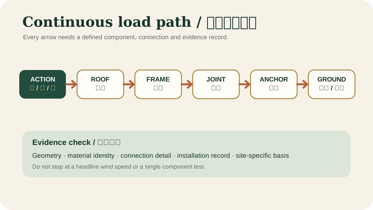
The diagram follows gravity, wind uplift and lateral actions from the roof surface into rafters or louvers, beams and posts. It continues through every connection, base plate and anchor into the foundation and finally the supporting soil, emphasizing that one weak or undocumented link interrupts the claimed structural path.
Key takeaways
- Keep controls out of drainage paths.View claim record ·
PWC-ELECTRICAL-MOTORIZATION-1 - Provide isolation and manual recovery.View claim record ·
PWC-ELECTRICAL-MOTORIZATION-2 - Automation sensors reduce risk but do not guarantee safe operation.View claim record ·
PWC-ELECTRICAL-MOTORIZATION-3
The claim register connects stable IDs, article locations and article-level associated sources; it is not an external fact-check of each statement.
On this page
System integration
Motors, power supplies, receivers, rain and wind sensors, heaters and lighting may share a frame but have different environmental and circuit requirements. Cable entries need strain relief, drip loops and compatible seals.
Commissioning
Record travel limits, obstruction response, emergency operation, control pairing and maintenance access. The handover should identify which devices operate automatically and what the owner must do before storms or freezing weather.
Official guidance for England covering structure, fire, moisture, drainage, access, electrical safety and workmanship.
Define the environmental boundary
Outdoor controls need documented enclosure suitability, cable-entry details, drainage, condensation management, protective devices, earthing or bonding and isolation. Components hidden inside posts are still outdoors if moisture can enter. Local electrical rules and a qualified installer determine the final arrangement.
Keep manual recovery possible
Handover should include isolator location, manual override, control pairing, travel limits, sensor thresholds, fault indications and safe access. A system that cannot be opened for drainage maintenance during a control failure creates a combined electrical and water-management problem. Record changes rather than repeatedly resetting unexplained faults.
Official abstract establishing a lifecycle framework from briefing and design through maintenance, replacement, reuse and disposal.
Separate drive safety from outdoor installation safety
IEC 60335-2-97 addresses hazards of electric drives used with awnings, blinds and similar equipment; CPSC guidance separately highlights weatherproof covers and ground-fault protection for outdoor receptacles. A compliant-looking motor label does not verify cable routing, isolation, water entry protection, controls, bonding, local code adoption or the complete moving pergola assembly. Coordinate the listed system instructions with the locally adopted electrical rules and qualified installation.
Evidence check before acting
This article provides general educational synthesis; these three checks turn reading into project-specific verification work.
| Confirm | Stronger evidence to retain | What this article cannot establish |
|---|---|---|
| Site actions, continuous load path, foundations, connections and supporting structure | Project-specific site data, calculations, approved drawings and inspection records | A general table, calculator or article is not a project design or approval. |
Registered cited sources and scope
Official guidance for England covering structure, fire, moisture, drainage, access, electrical safety and workmanship.
Official abstract establishing a lifecycle framework from briefing and design through maintenance, replacement, reuse and disposal.
International safety requirements for household and similar electric drives used with shutters, awnings, blinds and related equipment. It does not replace local electrical installation rules or verify a complete pergola system.
Government consumer guidance on weatherproof covers, outdoor receptacles and ground-fault protection. Adopted electrical codes and qualified installation remain project-specific.
Cite this page
Pergola Wiki Editorial Team. “Motors, controls and electrical safety.” Pergola Wiki. Content version 1.7; editorially reviewed 25 Jul 2026. https://pergola.wiki/articles/electrical-motorization/